


NewsDetails
How to verify and enhance the absolute positioning accuracy of the 3D flexible soldering platform?
author:admin time:2026-01-17 14:27:04 click:60
Verifying and enhancing the absolute positioning accuracy of a 3D flexible soldering platform is a systematic project,encompassing multiple levels from equipment fundamentals to advanced compensation techniques.The following are specific steps and methods:
1.Verify absolute positioning accuracy
Validation is the prerequisite for improvement,and it is essential to establish precise measurement benchmarks.
Establish measurement benchmarks and prepare equipment
Equipment warm-up:Allow the platform to operate at normal working speed and load for more than 30 minutes to ensure the mechanical structure reaches a thermally stable state.
Environmental control:Measurements should be conducted in an environment with constant temperature(such as 20±1°C),low vibration,and no strong airflow.
Choose high-precision measuring tools:Use laser interferometers(for linear axes)and laser trackers or high-precision ballbar instruments(for spatial accuracy and rotational axes)as the gold standard.Gauge blocks,micrometer,etc.can be used as auxiliary quick inspection tools.
Perform accuracy testing
Single-axis positioning accuracy(linear axis):
Using a laser interferometer,multiple target points are selected at preset intervals(such as every 50mm or 100mm)along each linear axis(X,Y,Z)within the full range of travel.
The command platform moves to each target point and records the actual position measured by the laser interferometer.
Calculate positioning error=actual position-commanded position.Through statistical analysis,obtain the unidirectional/bidirectional positioning accuracy,repeatability,and backlash of the axis.
Volumetric Accuracy:
This is the most crucial and comprehensive indicator.Use a laser tracker or a 9-line/14-line ballbar.
Define a series of 3D space diagonal points or grid points within the platform workspace.
Instruct the welding torch tip(or measurement target ball)to move to these three-dimensional points,and record the deviation between the instructed position and the actual position.
Analyze the three-dimensional error vectors of all measurement points to obtain the maximum error,average error,and error distribution pattern within the workspace.
Multi-axis linkage accuracy:
Perform circular or diagonal tests(such as circles on the XY plane).Using a ballbar,one can visually measure the roundness error and identify issues such as servo matching,perpendicularity,and backlash of each axis.
Data analysis and error modeling
Organize the large amount of error data obtained from measurements into an error graph or error table.
Analyze the regularity of the error:is it a systematic error(such as linearity error,perpendicularity error,thermal expansion)or a random error(such as guide rail wear,vibration)?
Provide data support for establishing error models(such as geometric error models and thermal error models)for subsequent software compensation.
II.Improve absolute positioning accuracy
Based on the verification results,we adopted a strategy of gradual improvement from hardware to software.
Fundamental mechanical adjustment and maintenance(to address the root cause)
Level and perpendicularity calibration:Use a precision electronic level and a collimation telescope to readjust the installation foundation level of the platform,as well as the mutual perpendicularity/parallelism between each linear axis.This is the foundation of all precision.
Inspection and adjustment of transmission system:
Backlash:Check the pre-tightening condition of the ball screw/gear rack,adjust or replace worn parts.
Straightness and flatness:Inspect the wear and straightness of the guide rail,and perform scraping or replacement if necessary.
Structural rigidity inspection:Ensure that all connectors and brackets are locked tightly without any looseness.For large platforms,the stability of the foundation needs to be checked.
Control system and servo parameter optimization
Servo tuning:Fine-tune the servo driver of each axis(proportional gain,integral gain,feedforward,etc.),optimize its dynamic response characteristics,and reduce following errors and overshoots.
Reduce vibration:By adjusting the filter parameters,mechanical resonance is suppressed,resulting in smooth and stable motion.
Software error compensation(the most commonly used and effective means of improvement)
Backlash compensation:Enter the measured backlash value in the CNC system,and the system will automatically compensate during direction change.
Pitch error compensation:
Based on the measurement data from the laser interferometer,a"pitch error compensation table"is generated within the control system.This table divides the full travel into several segments and assigns a compensation value to each point.When the axis moves to that specific area,the system will automatically fine-tune the command to offset the systematic error.
Spatial error compensation:
This is the most advanced compensation method.By utilizing three-dimensional spatial error data measured by a laser tracker,a spatial error compensation model for the entire workspace is established through mathematical modeling(such as polynomial fitting,neural networks,or rigid body models).
Integrate the model into the control system(usually an advanced numerical control system or third-party compensation software).Before executing any spatial positioning instructions,the system will predict the error of the point based on the model and make pre-correction to the instruction position.
Thermal expansion compensation:
Install temperature sensors at key locations to monitor the temperature of the screw,bearings,and the environment in real time.
Establish a thermal error model,and the control system will correct the positioning instructions in real-time based on temperature rise.
End-effector and calibration
Tool center point calibration:The TCP of the welding torch must be precisely calibrated.Any error in TCP will be directly reflected as a positional error of the welding point.Regular calibration should be performed using a high-precision 3D probe or TCP calibrator.
Workpiece coordinate system calibration:Utilize a touch probe or vision system to precisely locate the workpiece reference and establish an accurate machining coordinate system.
III.Establish a long-term accuracy assurance system
Develop a regular calibration plan:Based on the frequency of use and operating conditions,develop an annual or semi-annual calibration plan for the laser interferometer/tracker.
Preventive maintenance:Regularly clean the guide rails,replace lubricating oil,and inspect cables and connectors.
Standardized operating procedures:including power-on preheating,TCP calibration,program verification,etc.
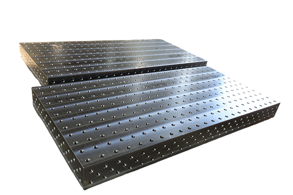
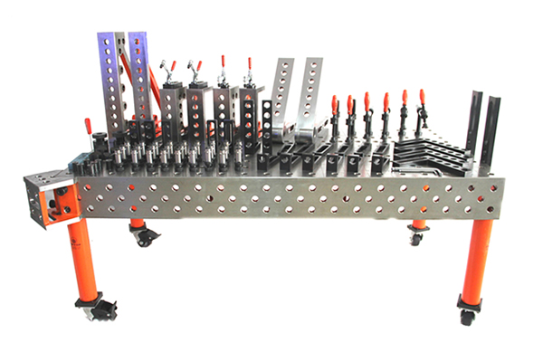
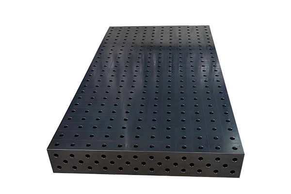
 Recommended Products
 Contact Us
—— Hotline:+86 13833738896
—— Hotline:+86 17332777263
—— Email:gongliliangju@163.com
—— Whatsapp:+8615832706206
—— Address:Beihan Village, Haocun Town, Botou City, Cangzhou City, Hebei Province, China