





NewsDetails
Hole-based Flexible Welding Platform Load Capacity: Engineering and Application Guide
author:jinchang time:2026-07-23 14:24:01 click:97
Load capacity is the parameter that separates a capable hole-based flexible welding platform from one that will fail under production demands. A platform that deflects under load produces distorted weldments regardless of how precisely it was machined. Understanding hole-based flexible welding platform load capacity - how it is specified, how it is affected by configuration, and how to verify it in your application - prevents costly purchasing mistakes and ensures safe, reliable operation at every weight range.
How Load Capacity Is Specified and What the Numbers Mean
Manufacturers specify hole-based flexible welding platform load capacity in kilograms or pounds, typically representing the maximum distributed load the platform can support without exceeding a defined deflection limit. Most specifications reference a deflection threshold of 0.05 mm at the center of the loaded area under full load. A platform rated at 1,000 kg means that a 1,000 kg workpiece distributed across the plate surface will deflect no more than 0.05 mm at its most critical point. Critically, this is a distributed load specification - concentrating the same 1,000 kg on a small footprint dramatically increases local deflection and can exceed local material strength limits even when the overall distributed load is within rated capacity.
Base Plate Thickness and Load Capacity Relationship
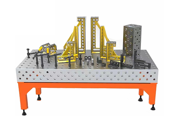
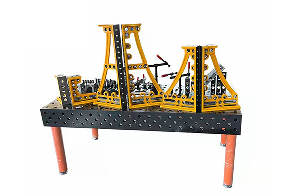
Base plate thickness is the primary determinant of hole-based flexible welding platform load capacity. A 25 mm cast iron plate typically supports 300-500 kg, a 40 mm plate supports 800-1,200 kg, and a 50-60 mm plate supports 1,500-3,000 kg depending on rib structure and material grade. Thickness affects bending rigidity according to the cube of thickness - doubling thickness increases rigidity by a factor of eight. This exponential relationship means that small increases in thickness produce large gains in load capacity, which explains why the price premium for thicker plates is justified by proportionally greater performance improvement.
Material Properties and Their Effect on Load Performance
The base plate material influences hole-based flexible welding platform load capacity in ways beyond simple stiffness. Cast iron provides the best combination of rigidity, vibration damping, and thermal stability for welding applications. Steel offers approximately twice the stiffness per unit volume compared to cast iron but exhibits higher thermal expansion and less favorable damping characteristics. Under welding thermal cycling, a steel plate distorts more readily than a cast iron plate even when both meet the same static load specification. For applications involving high-amperage welding or extended weld cycles, cast iron platforms typically outperform steel platforms in long-term dimensional stability even if initial deflection measurements appear equivalent.
The Role of Rib Structure in Load Distribution
The internal rib structure beneath the working surface of a hole-based flexible welding platform significantly amplifies its effective load capacity beyond what plate thickness alone would suggest. A well-designed rib pattern distributes concentrated loads across a wider area of the plate, reducing local deflection at the load point. Ribs oriented perpendicular to the expected primary load path provide the greatest stiffening effect. When evaluating platform specifications, examine whether the load rating accounts for rib structure. Platforms with optimized rib designs achieve 30-50 percent higher load capacity than flat-plate designs of the same thickness and material.
Point Load vs. Distributed Load Considerations
Understanding the difference between point load and distributed load is essential for accurate hole-based flexible welding platform load capacity assessment. A point load concentrates the full workpiece weight on a small contact area - for example, a heavy casting setting on its four corner feet rather than distributed across its full base. Point loads dramatically reduce effective load capacity because local stress exceeds what the plate surface can support without deformation. Always distribute heavy loads using backing plates, support grids, or wide-foot support posts. A 1,000 kg workpiece distributed across a full 500 mm by 500 mm footprint stresses the platform far less than the same 1,000 kg concentrated on four 50 mm by 50 mm contact points.
Dynamic Load Factors in Welding Applications
Welding operations impose dynamic loads that exceed static workpiece weight. Thermal expansion during welding creates internal forces that effectively multiply the static load by a factor of 1.5 to 2.5 depending on weld intensity and part geometry. Arc force from high-amperage processes adds transient loading that further stresses the platform. A hole-based flexible welding platform load capacity specification that ignores these dynamic factors understates the actual loading condition. When calculating the required load capacity for a welding application, multiply the static workpiece weight by 2 as a conservative dynamic factor, or by 1.5 for low-heat processes such as TIG welding on thin materials.
Support Configuration and Effective Load Capacity
The way a hole-based flexible welding platform is supported beneath its mounting points affects its effective load capacity. Platforms mounted on rigid steel legs achieve their full rated capacity. Platforms on adjustable height posts with less rigid connections may reduce effective capacity by 10-20 percent due to the compliance of the support connections. Platforms supported on caster wheels experience additional stress from point loading at each wheel contact. Always verify that support leg or leg configurations match the manufacturer's requirements, and avoid modifying support arrangements without engineering evaluation.
FAQ: Hole-based Flexible Welding Platform Load Capacity
What load capacity do I need for a 500 kg workpiece?
Apply a 2x safety factor for welding dynamic loads. A 500 kg workpiece effectively requires a platform rated for 1,000 kg static capacity. Select a 40 mm cast iron plate or equivalent to provide adequate margin for thermal and arc forces during welding.
Can I exceed the rated load capacity temporarily?
No. Exceeding rated load risks permanent deformation of the base plate. Even a single overload event that does not cause visible damage can introduce internal stresses that accelerate future degradation and distort the plate's flatness beyond specification.
How does support leg configuration affect load capacity?
Rigid support legs preserve full rated capacity. Adjustable-height posts with flexible connections may reduce effective capacity by 10-20 percent. Caster wheels introduce additional point-loading stress. Always follow manufacturer recommendations for support configuration.
What is the difference between static and dynamic load capacity?
Static load capacity is the maximum weight the platform supports without exceeding a deflection limit under steady conditions. Dynamic load capacity accounts for transient forces from welding heat, arc pressure, and thermal cycling. For welding applications, always evaluate dynamic conditions.
Conclusion
Accurate understanding of hole-based flexible welding platform load capacity prevents both under-purchasing (resulting in deflection and quality problems) and over-purchasing (resulting in unnecessary cost). Key principles include: selecting plate thickness based on maximum distributed load with a 2x safety factor for welding dynamic loads, preferring cast iron for thermal stability, verifying that rib structure is included in the manufacturer's rating, distributing concentrated loads across wide contact areas, and maintaining support configurations as specified by the manufacturer. Applying these principles ensures the selected platform delivers reliable performance throughout its service life.
References
Bi, Z.M. and Zhang, W.J. (2001). Flexible fixture design and automation: Review and future directions. International Journal of Advanced Manufacturing Technology, 17(4), 266-277.
Rong, Y. and Bai, Y. (2000). Modular fixture element assembly and accuracy analysis. International Journal of Production Research, 38(14), 3103-3114.
Kumar, S. and Nee, A.Y.C. (1995). Development of a modular fixture design system. Journal of Intelligent Manufacturing, 6(4), 263-274.
Wang, Y. et al. (2019). Distortion mitigation in automotive welding through optimized clamping sequences. Journal of Materials Processing Technology, 270, 188-199.
 Recommended Products
 Contact Us
—— Hotline:+86 13833738896
—— Hotline:+86 17332777263
—— Email:gongliliangju@163.com
—— Whatsapp:+8615832706206
—— Whatsapp:+8615931710409
—— Address:Beihan Village, Haocun Town, Botou City, Cangzhou City, Hebei Province, China